ZenCAM Installation
1.Introduction
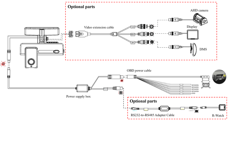
2.System Overview
ZenCAM offers different models to suit various installation needs:
2.1.No Power Box:
- Needs to be hardwired.
- Suitable for standard installations for dual channel setup.
2.2.Standard Power Box:
- Can be hardwired or installed through the OBD port.
- Suitable for standard installations with 2 channels expansion.
2.3.Diagnostics Box:
- Can be hardwired or installed through the OBD port.
- Ideal for installations requiring vehicle diagnostics integration.
2.4.Power Box Max:
- Allows expandability to six channels.
- Can be hardwired or powered through OBD port.
- Perfect for complex setups requiring multiple camera channels.
3.Pre-Installation Checklist
3.1.Tools & Equipment
| 1 | Common screwdriver kit | Tighten screws, optional | 1pc | |
| 2 | Crowbar | Pry up the vehicle panel | 1pc | |
| 3 | Ties | Bundle cables | Prepare as needed | |
| 4 | Dry cleaning cloth | Clean the dashboard | 1pc | |
| 5 | Mobile phone/Pad | Install the Veyes App for video preview and parameter configuration | 1pc | |
| 6 | Steel tape | Measure the installation height of the forward-facing ADAS lens and assist the installation in other scenarios | 1pc | |
| 7 | Mark pen | Mark lines for Dashcam installation | 1pc | |
| 8 | Cutting nippers | Cut and strip wires | 1pc | |
| 9 | Insulated rubber tape | Wrap wire ends | 1pc | |
| 10 | Scissors | Cut insulated rubber tape or wire clip | 1pc | |
| 11 | Multimeter | Locate vehicle power supply, measure the conduction of harness, and measure pulse signal | 1pc | |
| 12 | Waterproof tape | Waterproof protection for outdoor wire connectors | 1pc | |
13 | Hole and Poke Tool | It is used to poke a wire to add external wire connections | 1 Set | |
14 | Fuse Add a Circuit | Connections To add a extra fuse line on the current running electrical fuse | 2 per Camera | |
15 | Fuse Link | To add fuse for safety before any external connection | 2 Per Camera | |
16 | Soldering Iron | It is used to solder the connection | 1 | |
17 | Soldering Tool | Need to solder | 1 | |
18 | Fuses | Use max 5 amp | As needed |
3.2.Safety Precautions
- Ensure the vehicle is turned off and parked in a safe, stable environment.
- The vehicle should be on a flat surface to prevent any movement during installation.
- Wear protective gear as necessary (gloves, eyewear).
4.Installation Process
4.1.Installation of SIM Card and Memory Card
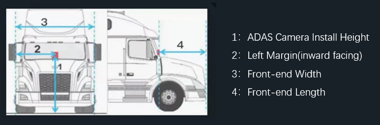
- Identify the recommended installation location on the windshield.
- Please refer to the below diagram to ensure correct placement, avoiding obstructions and without blocking driver view
Tear off the 3M adhesive tape, install the bracket horizontally on the target installation area of the front windshield (the upper edge of the bracket should be parallel to the upper edge of the windshield) according to the direction indicated by the arrow on the bracket, and press the bracket for 10s to ensure that no air bubbles remain between the bracket and the glass.
4.3.Installation of Dashcam
4.4.Angle Adjustment and Fixation of Dashcam
- Adjust the Dashcam back and forth so that it is vertical.
- Fasten the bracket stud to ensure that the angle of the Dashcam will not be changed easily, and fix the Dashcam.
- The center of the cockpit shall be in the middle of the screen.
- The cockpit screen shall be horizontal.
- The vehicle steering wheel shall be shown at the lower left/right corner of the screen.
- Make sure that the connection between the bracket and the Dashcam is fastened (the device is rigidly connected with the vehicle), so that the Dashcam will not shake easily. Otherwise, the GPS positioning will be inaccurate.
- Only after the Dashcam is firmly connected with the vehicle can the device be powered on.
- If the device is fixed and installed after power-on, it shall be powered on again before being tested or used.
5.Wiring and Power Connection
For Hardwire Models:
- Run the cable through the vehicle’s headliner to the fuse box.
- Ensure the power box is firmly mounted
- Connect the respective wires to the fuse box
For OBD Models:
- Run the cable through the vehicle’s headliner to the OBD port
- Ensure power box is firmly mounted
- Connect the camera’s OBD connector to the vehicle’s OBD port.
5.1.No Power Box (ZenCAM LITE)
- After mounting the camera on the windshield connect the camera to the Power Cable and run the cable through the vehicle's headliner to either the OBD port or the fuse box based on the preferred installation method.
- If you are using the OBD connection then run the cable next to the OBD port and secure the connection
- If you are hardwiring the connection then run the cable next to the fuse box and below is how the wired needs to be connected:
- Red wire to constant power
- Orange wire to Ignition power
- Black wire to ground
5.2.Standard Power Box (ZenCAM Plus & ZenduCAM ADAS-D+1)
- After mounting the camera on the windshield connect the camera to the Power Supply Box and run the cable through the vehicle's headliner to either the OBD port or the fuse box based on the preferred installation method and ensure Power Box is firmly mounted
- If you are using the OBD connection then run the cables next to the OBD port and and secure the connection
- If you are hardwiring the connection then run the cable next to fuse box and below is how the wires need to be connected:
- Red wire to constant power
- Orange wire to Ignition power
- Black wire to ground
 5.3.Diagnostics Box (ZenCAM PLUS)
- After mounting the camera on the windshield connect the camera to the Host connecting cable and run the cable through the vehicle's headliner to either the OBD port or the fuse box based on the preferred installation method and ensure Power Box is firmly mounted
- If you are using the OBD connection, then after running the cables next to the OBD port, connect the cables to the Power Box Plus, firmly mount the Power Box and then connect it to the 16PIN OBD connection cable and secure the connection
- If you are hardwiring the connection, then after running the cables next to the Fuse Box, connect the cable to the Power Box Plus, firmly mount the Power Box and then connect it to the Hardwire connection cable and secure the connection to the fuse box as shown below
- Red wire to constant power
- Black wire to ground
5.4.Power Box Max (ZenCAM PLUS)
- After mounting the camera on the windshield connect the camera to the Power & Signal Connection Cable and Network Port Connection Cable and run the cables through the vehicle's headliner to either the OBD port or the fuse box based on the preferred installation method and ensure Power Box Max is firmly mounted
- If you are using the OBD connection, then after running the cables next to the OBD port, connect the cables to the Power Box Max, firmly mount the Power Box and then connect it to the 16PIN OBD connection cable and secure the connection
- If you are hardwiring the connection, then after running the cables next to the Fuse Box, connect the cables to the Power Box Max, firmly mount the Power Box and then connect it to the Hardwire connection cable and secure the connection to the fuse box as shown below
- Red wire to constant power
- Orange wire to Ignition power
- Black wire to ground
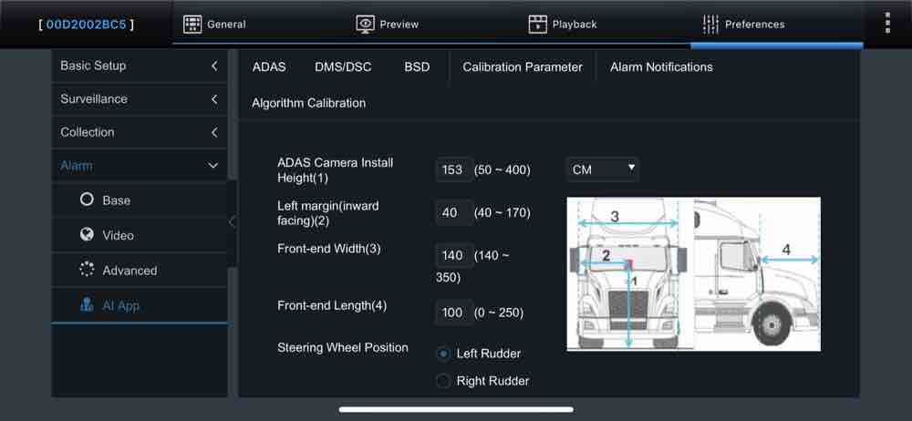
6.Calibration and Configuration
6.1.ADAS Calibration Setup
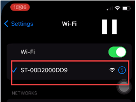
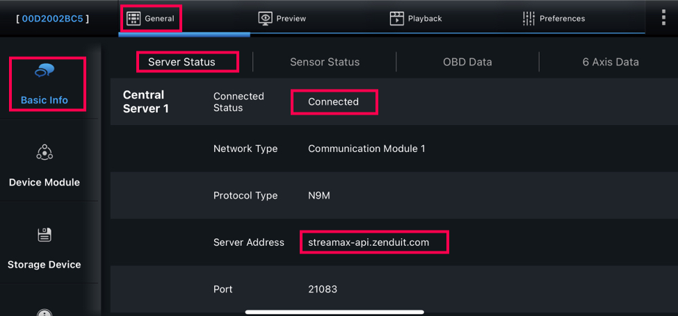
Connect to Wi-Fi. (Ensure connected to camera 003F or 00D2 or 00710).
Launch Veyes application and ensure you are connected to the camera and enter the following credentials:
Username: admin
Password: For password contact our support at support@zenduit.com +1 (855) 936-3848 x 2
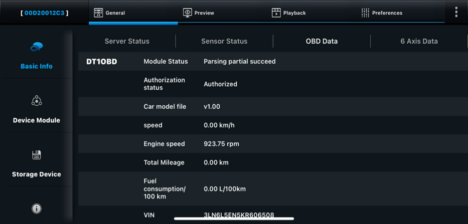
6.2.Diagnostic File Setup
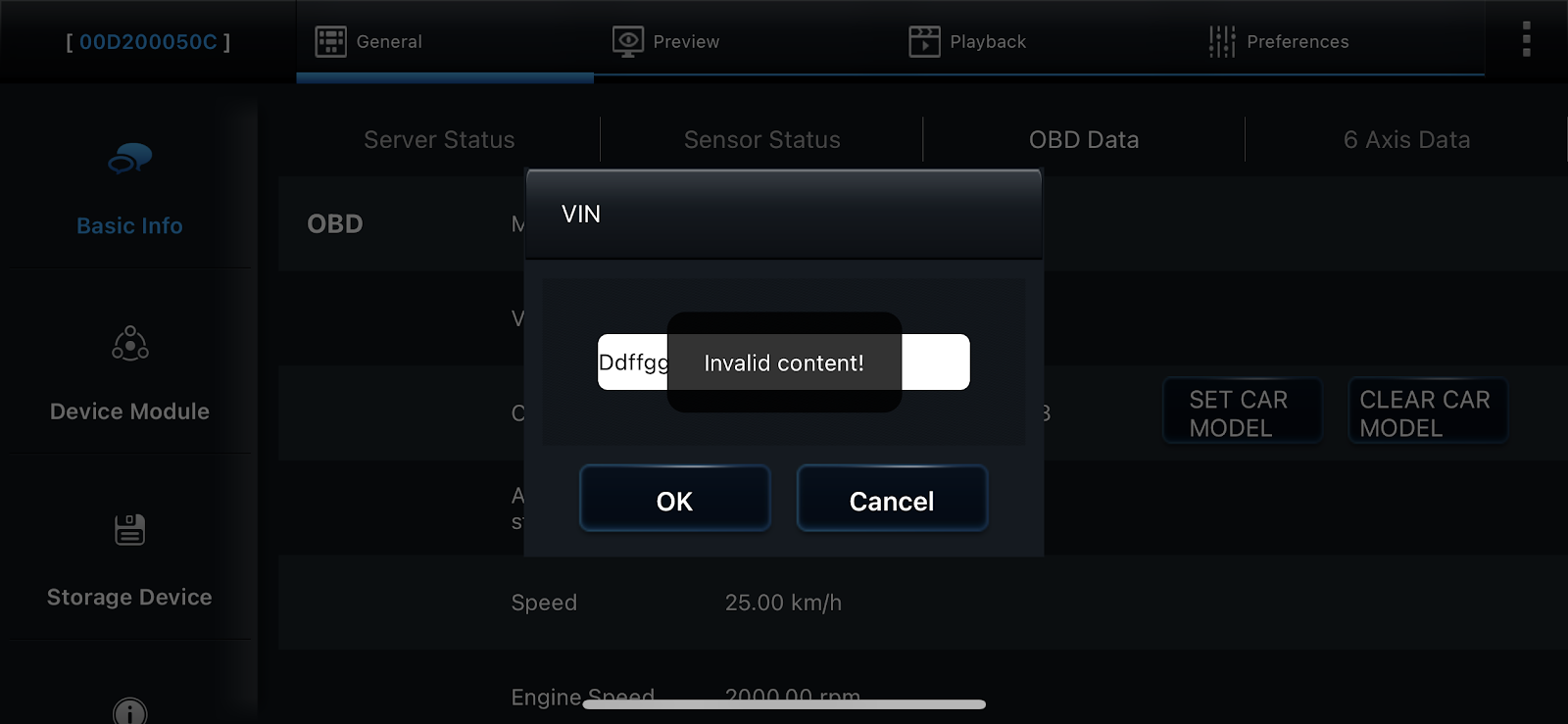
After inputting the VIN, click on SET CAR MODEL to enter the setting model interface.
Select the corresponding vehicle type according to the brand information of the vehicle
After selecting the corresponding model, click Set to upgrade the model file online and wait for the upgrade result of the model file
Result is the upgrade result display area, and the Task Completed indicates that the upgrade is successful. After the upgrade is successful, data verification and testing can begin
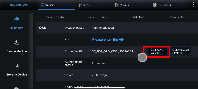
Ensure OBD data coming in the list below, some data points won’t be available as the car model do not support them

2. This product only supports original models, not modified vehicles. If instrument failure is caused by docking modified vehicles, please be responsible for all consequences!
3. When replacing the vehicle, in order to ensure that the device will not send the agreement content of the previous vehicle, resulting in instrument failure, click 【CLEAR CAR MODEL】 before disassembly and assembly.
6.3.Power Box MAX Expandability Setup
6.4. Input Sensors Setup
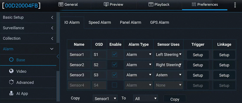
The device is equipped with a conventional power box and supports up to 10 inputs, including 4 IO inputs.
IO Alarm Screen Overview:
Serial Number:
Options include Sensor1, Sensor2, Sensor3, and Sensor (up to eight IO inputs are supported when using the UPS power box).
Name:
Sensor names can be customized or modified to suit specific requirements.
OSD (On-Screen Display):
Represents the sensor name abbreviation, which can be customized for OSD superimposition.
Alarm Type:
Options are Alarm or Event.When Alarm Type is set to Alarm:
The alarm is superimposed on both the preview screen and recorded footage.
The alarm is uploaded to the platform.
Alarm logs are recorded.
When Alarm Type is set to Event:
OSD superimposition is enabled.
The alarm is not reported to the platform.
Alarm logs are recorded.
Sensor Uses:
Defines the purpose of the sensor, which can include:Left Steering
Right Steering
Brake
Privacy
Trigger Settings:
Tap Setup to access the configuration screen for sensor triggers.

1) Trigger Settings:
High: Normal state is Low; it switches to High when triggered.
Low: Normal state is High; it switches to Low when triggered.
Pulse: Normal state is Low; the state fluctuates when triggered.
 Voltage Detection:
The voltage at the 0 port can range from 0 to 36V. Values below 5V are considered Low, and values above 3.5V are considered High. Ensure that the device operates within this range to avoid damage. Note: Strsamas is not responsible for any device damage caused by exceeding the detectable voltage range.
2) Effective Alarm Time:
Value Range: 0–10 seconds (default is 5 seconds).
Example: If a motion detection alarm is triggered at 13:23:30 and cleared at 13:23:50, setting the effective time to 10 seconds means that any new motion detection alarm triggered within the next 10 seconds will be considered part of the same alarm. This prevents multiple redundant entries in the alarm log.
7.Post-Installation
- Check the camera feed on the ZenCAM dashboard.
- Test for clear video feed and proper recording.
- Refer to the troubleshooting section if issues arise.
8.Troubleshooting and Support
Related Articles
ZenCAM M1N Installation
Schematic Diagram of Equipment Connection List Of Product Material Product Name Picture Notes M1N DVR Unit Main DVR unit which cameras, power, Cellular/GPS/WIFI Antenna will be connected to MINI key Key needed to unlock the M1N 9 PIN power cable ...ZenCAM Wireless Camera Installation
System Composition: System Wiring: Installation Step 1: Insert the SIM and TF cards Take out the Dashcam (power-off), and use the Allen key in the kit to open the card slot panel on the right of the Dashcam by turning counterclockwise. Install SIM ...ZenCAM Lite - Specification Sheet
DOWNLOAD PDFZenCAM Plus - Specification Sheet
DOWNLOAD PDFZenCAM X3N DVR Install
ZenCAM X3N Installation Guide Schematic Diagram of Equipment Connection List Of Product Material Product Name Picture Notes X3N DVR Unit Main DVR unit which cameras, power, Cellular/GPS/WIFI Antenna will be connected to MINI key Key needed to unlock ...